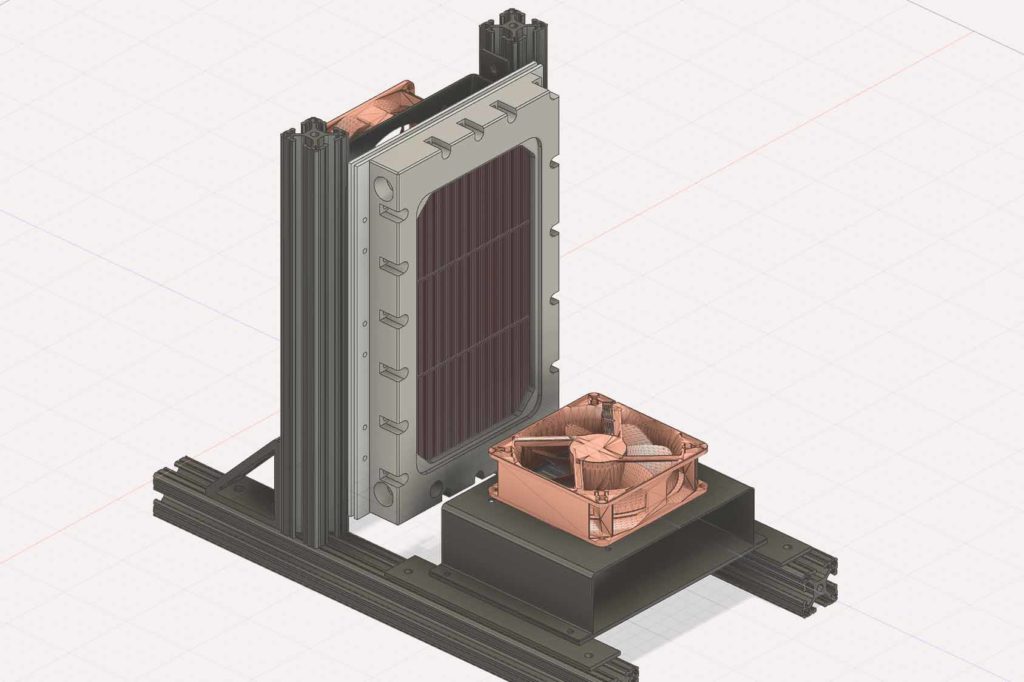
An ongoing project aims to design an efficient heat exchanger powered by a series of six Thermoelectric (TE) modules as apart of a subassembly for BellaMia Technologies. The primary challenges involve effectively managing heat dissipation from the TE modules and optimizing airflow through the heat exchanger to achieve optimal temperature differentials and minimal pressure drops. To address these challenges, Ansys Fluent, a leading computational fluid dynamics software package, was used. This software is instrumental in simulating fluid flow, heat transfer, and fluid-structure interactions, thereby aiding in the design and optimization process.
Project Requirements:
Several conditions were set forth at the project’s outset:
- Size limitations for the overall Air Chiller assembly and the heat exchanger manifold.
- Attainment of a minimum temperature of -20°C.
- Maintenance of a constant temperature of -10°C at the cold plate for intervals of up to 30 minutes.
- Reduction of the incoming air temperature from approximately 43°C to 2°C as it exits the manifold, also for 30-minute intervals.
Addressing Constraints:
A significant challenge lies in maintaining a constant temperature of -10°C at the cold plate without risking overheating. To meet this challenge, the TEC1-12715 TE module series was selected for their larger surface area and higher wattage rating, ensuring a sufficient temperature differential (delta-T). Powering these modules necessitates two AC-DC power supplies, each delivering 24V at 18.8A. Consequently, considerable heat is generated, requiring efficient heat dissipation methods. To facilitate this heat dissipation, 1/8-inch copper sheets will be utilized, with an identical sheet employed on the cold side. Copper’s selection is due to its exceptional thermal conductivity, enabling rapid heat transfer. Additionally, copper boasts corrosion resistance, attributed to its ability to develop a protective oxide layer on its surface, reducing further corrosion. The copper sheet on the hot side of the TE module serves to dissipate heat generated by the modules. An array of six copper skived fin heat sinks will be attached with thermal gap material in between the copper surfaces. Skived heatsinks are crafted using a skiving machine, which slices materials into thin fins, subsequently pushing them up to maximize surface area for efficient heat dissipation.
For those intrigued by the manufacturing process of skived fin heat sinks, a demonstration can be viewed in the following video:
https://www.youtube.com/watch?v=wsglQFjTZ_c&t=64s
Designing the Cold Plate Assembly: Similar to the hot side, the cold plate assembly comprises three larger copper skived fin heat sinks arranged to transfer heat from the passing air into the system. A machined Nylon manifold facilitates an airflow through the heat sinks in a controlled manner, ensuring uniform heat distribution and minimizing hot spots.
The manifold piece must include both an inlet and an outlet to accommodate incoming and exiting air. The incoming air is sourced from a Gust 87R Rocking Piston compressor, capable of supplying a maximum pressure of 30 psi. It has been recorded to deliver 90 liters per minute through 1/2 inch tubing.
Simulation and Analysis:
The challenge lies in effectively routing the incoming air to ensure even dispersion throughout the heat exchanger, thereby preventing significant hot spots within the manifold. This challenge is closely linked with the objective of achieving the greatest temperature difference and the lowest pressure drop.
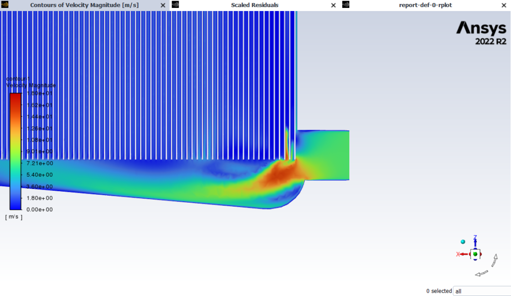
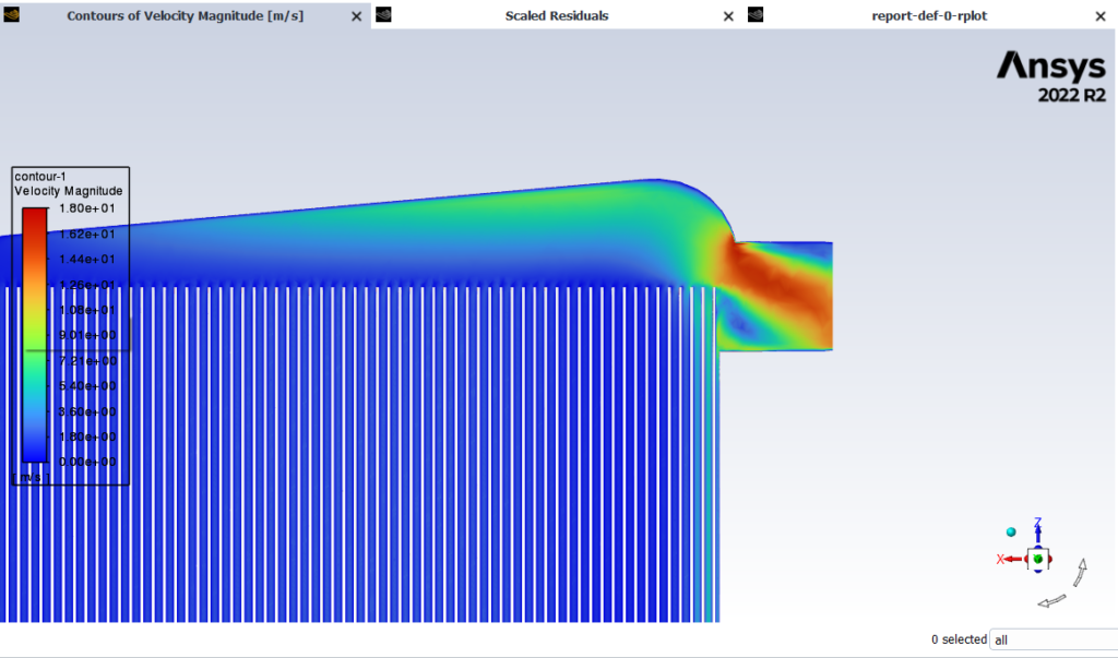
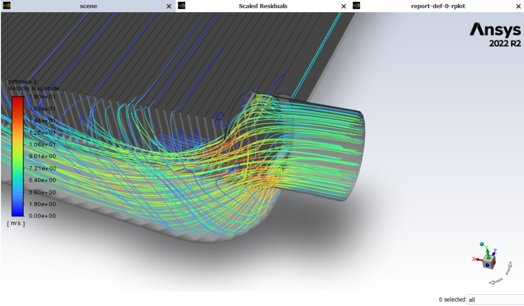
To address these issues, Ansys Fluent was used to assess various designs and quantify key parameters. These simulations aimed to evaluate pressure changes, identify locations of unwanted turbulence, and ongoing simulations are being conducted to ascertain temperature differences within the system.
The data obtained guided improvements to the current heat exchanger system, including modifications to the manifold design to optimize airflow and heat dissipation.
Presently, the heat exchanger manifold was crafted prior to conducting Ansys simulations. Despite this, I successfully simulated the existing design to implement necessary modifications. Subsequently, new manifold components will be fabricated based on insights from simulation and analysis of the other manifold designs. Below are the images showcasing the current design. Notably, you will notice that the heat sinks are impeding the manifold entrance. Consequently, I accurately measured the constraints and enacted modifications on the physical component.
Images if current heat exchanger with Ansys Fluent:
Images of showing the before and after adding gap material:
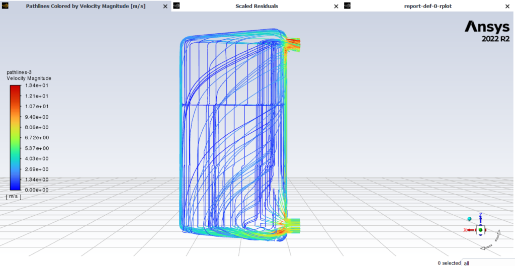
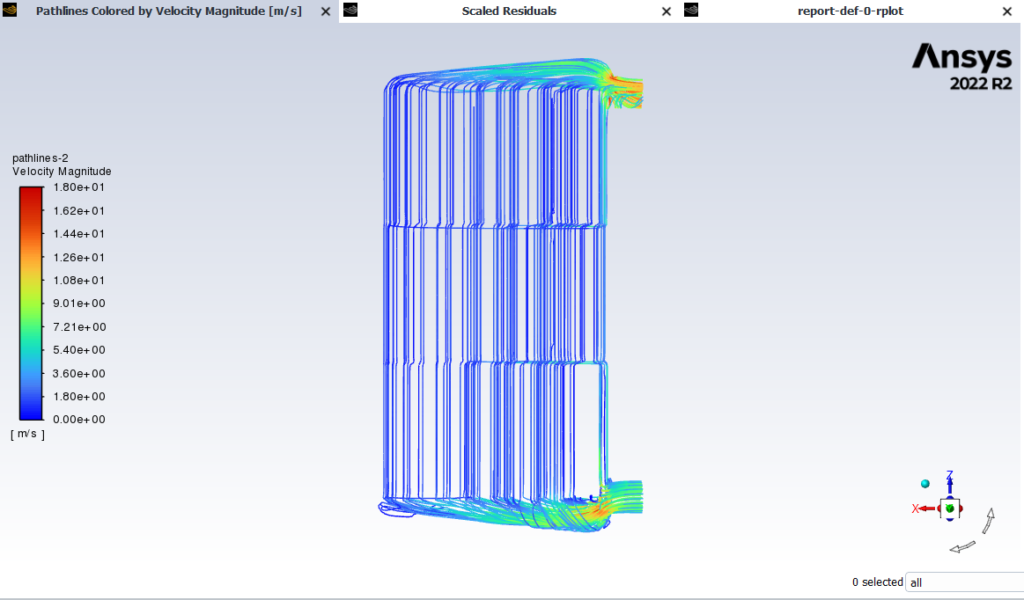
What is important to notice in the image before the gap material (fg. 1) there is large volumes of air flow around the sides and over the top of the heat sinks. With the addition of the material, a greater volume of air now flows through the heat sinks, evidence by the linear path of the pathlines. However there are still hot spots and concestion points with this particular design. Fortunately, the new manifold will account for these issues.
It is important to note in the image prior to the introduction of the gap material (see fig. 1), significant volumes of airflow surround the sides and pass over the top of the heat sinks. Following the addition of the material, a larger volume of air now traverses through the heat sinks, as indicated by the linear routes of the pathlines. Nevertheless, certain hot spots and congestion points persist in this design. Thankfully, the upcomming manifold redesign will address these concerns.
Transition to Physical Testing:
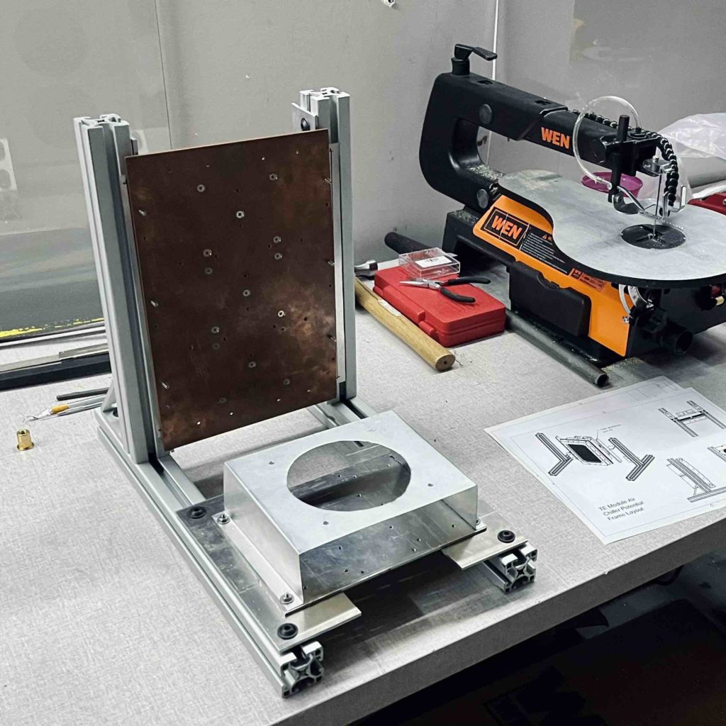
Following thorough analysis and simulation, the project transitioned to the construction phase. Metal extrusions were utilized to construct the frame, with adapter plates facilitating connections between the heat exchanger and the power regulator frame.
Current Project Stage:
At the moment, the project is in the testing phase, aimed at validating the simulations through physical testing. Future iterations will incorporate insights gleaned from testing to further refine and optimize the heat exchanger design.
