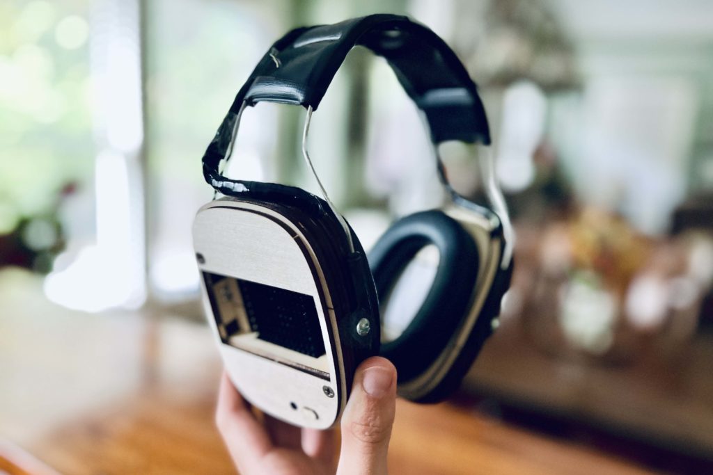
Imagine a world where you can find respite from the discomfort of red and unbearably hot ears, regardless of the conditions you find yourself in. While this may not be a concern for everyone, the frustration of red and uncomfortably hot ears is a common symptom experienced by individuals with sunburns, high temperatures, otitis media, and red ear syndromes. Recognizing the need for a practical and effective solution as well as an opportunity for continued development of practical skills, I created an innovative earmuff that would not only provide cooling relief but also embody the principles of functionality, convenience, portability, aesthetics, and comfort for those seeking relief from the discomfort of red and hot ears.
The Vision: Setting the Constraints
An obvious solution would be to strap some ice packs to headphones and call it a day. However, this approach would not allow for temperature adjustability while in use, long cooling periods, self-sufficiency from freezers, and other tethers. Rather, I wanted to create a solution that not only provided cooling relief for ears but also met specific requirements. My constraints were as follows:
- Adjustable Cooling: The device should offer adjustable cooling, allowing users to tailor the temperature to their comfort.
- Portability: It needed to be self-sufficient, free from the need for an external power source or the hassle of refrigeration.
- Compactness: I aimed for a compact and ergonomic design for maximum comfort.
- Energy Efficiency: To ensure extended usage, I wanted to minimize power consumption lowering the need for larger battery storage.
The Coolmuff Core: Thermoelectric Modules
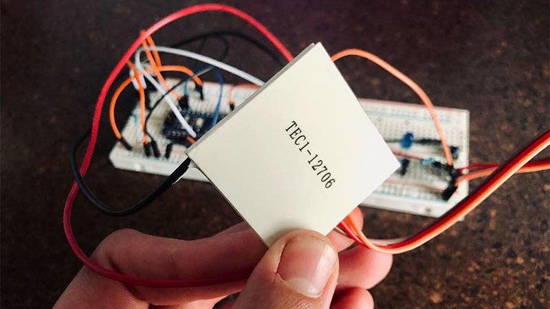
To meet these constraints, I chose thermoelectric (TE) modules, also known as Peltier modules, as the heart of Coolmuffs. TE modules work by applying a low voltage DC power, causing heat to move from one side to the other, creating a cooling effect on one side and heating on the other (Ferrotec). This property makes TE modules ideal for my project, offering compactness and controllability. With a proper setup (such as with stacking and greater density modules), TE modules can reach temperatures as low as -40º F (-40º C), providing a wide temperature range for cooling applications. However, for my needs, I will only need to reach around 70º F, with an average 18º F temperature difference.
Challenges in Temperature Control
One of the challenges in the Coolmuffs project was achieving temperature control. The initial solution involved using a potentiometer to manually adjust the power supplied to the TE modules, allowing for temperature regulation. However, my goal was to create a system that could automatically adjust the temperature based on the wearer’s needs.
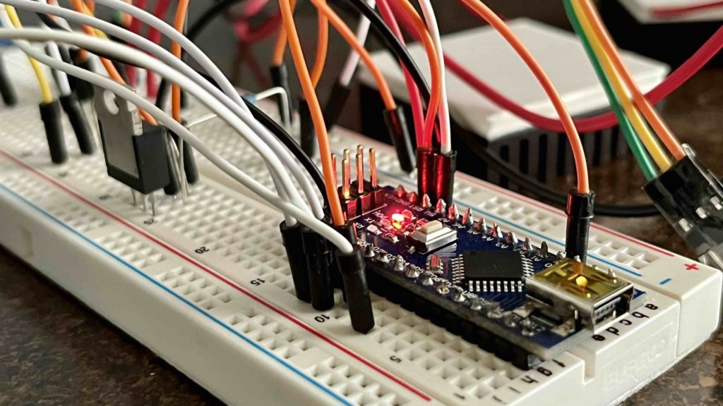
To tackle this issue, I replaced the less attractive manual potentiometer solution with an N-Channel MOSFET P-Type transistor, controlled by an Arduino Nano. This selection was based on the MOSFET’s capability to control current flow through voltage applied to its gate terminal. This transistor allowed me to control the higher voltage from two 9V batteries using a low-voltage PWM pin from the Arduino Nano. The Arduino Nano was chosen for its small form factor and versatility. To monitor the temperature of the cooling side of the TE module, I incorporated an LM35 temperature sensor into the system. By continuously measuring the temperature, the Arduino could adjust the voltage supplied to the TE module, maintaining a consistent cooling effect.
Programming
For the programming of the Coolmuffs, I used Arduino IDE 1.8.19 with C++. The code represents a negative feedback loop in the code to maintain the device at an optimal temperature of around 70°F. When the Coolmuffs are activated, the LM35 temperature sensor detects the temperature. The Arduino responds by increasing or decreasing the voltage supplied to the TE module, thereby regulating the TE until the desired temperature is achieved.
In addition to the primary cooling functionality, I implemented a toggle button to interrupt the voltage supply to the TE module and put the Arduino into a sleep state when the device is not in use. This feature prevents unnecessary battery drainage when the Coolmuffs are not in use, enhancing their overall convenience and portability – link to Arduino guide to low power design.
Testing and Refinement
I began the prototyping phase using a breadboard, providing flexibility to experiment with various layouts, codes, and components. However, I encountered a challenge of inconsistent test results. While the system initially functioned well, I noticed a significant drop in voltage from the MOSFET drain after conducting multiple tests in quick succession. This irregularity prompted an investigation into potential causes, leading me to consider the influence of voltage spikes generated by the inductor when its power supply underwent sudden reduction or removal. I identified the inductive load as the TE modules, with power supplied by disconnecting 9V batteries (as I lacked a bench power supply).
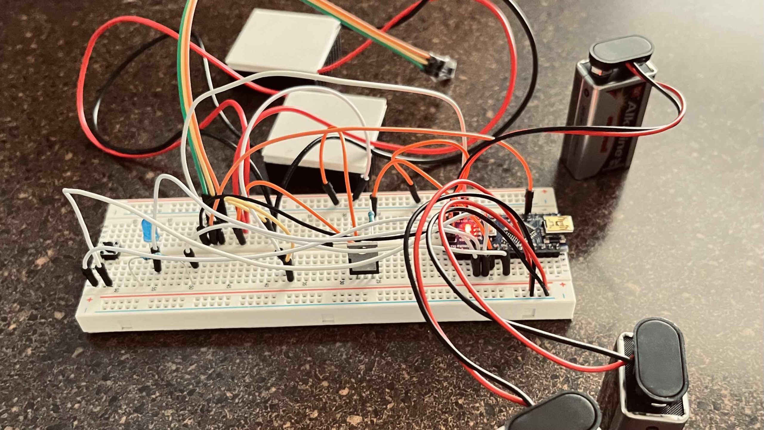
To address this issue, I implemented a solution by introducing a flyback diode in parallel with the TE modules and the battery. This modification effectively resolved the problem, eliminating subsequent instances of voltage drops in controlling the TE modules.
TE modules can achieve temperatures well below what is required for cooling the ears effectively. For this project, I needed to maintain temperatures between 65º to 70º F (~19.7º C). Testing for temperature control demonstrated that TE modules can indeed consistently remain at this desired temperature.
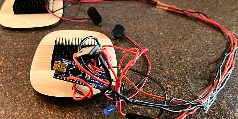
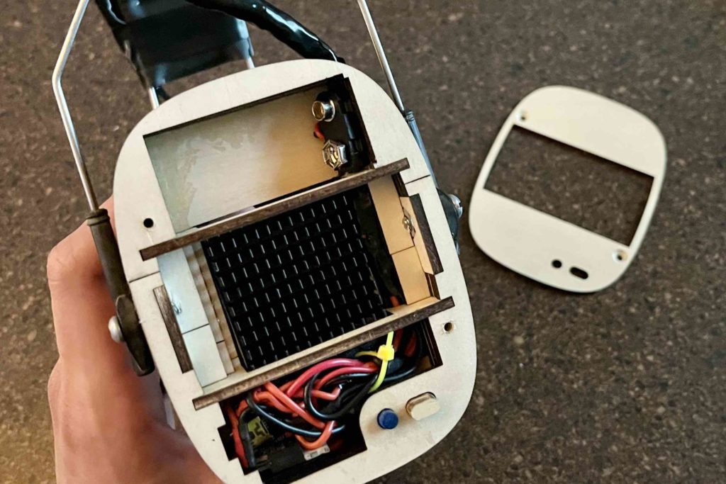
After finalizing the optimal wiring layout, I transitioned from the breadboarded prototype to a more permanent setup, significantly reducing the size of the electrical system. This involved soldering all the components directly to the Arduino Nano and ensuring joints were insulated with heat shrink or electrical tape to prevent shorts. It was also necessary to ensure that the setup minimizes waste in length of wire as the components were destined for a confined space.
Designing the Frame
Moving to the frame design phase, I had specific expectations:
- Laser-cuttable
- Small and slim form factor
- Compatible with the headband from a pair of Peltor earmuffs
- Comfortable to wear
- Heat sink ventilation
- Aesthetic appeal
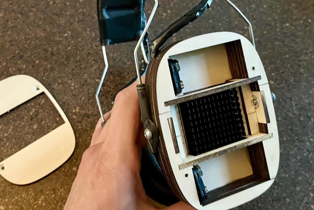
Brainstorming various layouts to minimize space, I settled on a design with dimensions of approximately 0.75” x 4.25” x 2.6”, incorporating rounded corners. Using Fusion 360, I dimensioned components based on this layout and designed the frame around digital elements. The laser cutted used for this project is an open frame diode laser from xTool, the D1 Pro model. The software used for cutting is LightBurn. To further fine-tune the tolerances for the frame cutout, I utilized the kerf features that are built into LightBurn. This precision ensured that the frame pieces would fit together seamlessly. For reference the plywood used is 0.112” thick (around 1/8th inch), this is reflected in the CAD model.
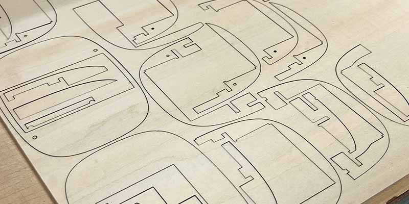
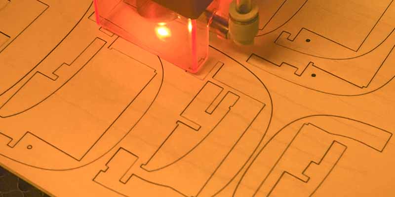
Assembling the Units
For the assembly, superglue was used. To facilitate this process, I incorporated features such as a lattice design. This allowed me to assemble two sides of one pair separately and join them after the glue had settled. Additionally, I included a reference point in the frame design—a vertical piece aligning the majority of the horizontal cutouts.
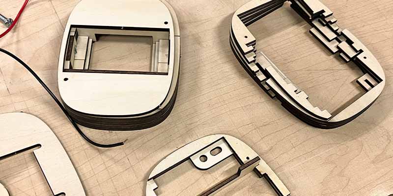
The final challenge involved fitting all the electrical components into the frame presented an unexpected challenge. While everything ultimately fit, it was a much tighter squeeze than anticipated. For the wiring between the units, I simply covered them with electrical tape, to maintain aesthetics. In retrospect, using a wiring harness would have been a neater solution.
Results and Reflection
In the end, the Coolmuffs project successfully achieved its goal, effectively chilling the cool side of the TE modules to a consistent 70º F (21º C). However, extended use or extremely hot days revealed a gradual warming of the cool side. The heat generated exceeded the electrical power input and the heat sink’s capacity to compensate for it.
For future improvements, I would consider:
- Using smaller gauge wire for the electrical system.
- Implementing a ribbon strip to wire the right and left units together.
- Adding a manual control for on/off.
- Creating a customized microcontroller, tailored specifically for the project’s needs.
- Replacing the 9V batteries with more efficient lithium-ion batteries.
If you have any questions, concerns, or would like to share tips or insights, please feel free to leave a comment below or contact me at hudsondeppen@gmail.com. Thank you for reading, and for more projects, you can explore my other creations on this website.
Parts List
N-Channel MOSFET P-Type RFP30N06LE transistor – WeiMeet RFP30N06LE 30A 60V N-Channel Power Mosfet TO-220 ESD Rated for Arduino(10 Pieces): Amazon.com: Industrial & Scientific
Resources
miracle-ear.com – Red and hot (burning) ears
matsusada.com – What is Thermoelectric Coolers
thermal.ferrotec.com – Introduction to Thermoelectric Cooling
